Viewing Historical Signal Changes
The Signal Display window provides a graphical view of control signal transitions that you can manipulate. You can zoom in to view the state of control signals for a range of events, or zoom out to view control signal changes over the course of an entire capture session.
To open this window click
the Signal Display icon  on the Control window toolbar,
or choose Signal Display from the Window menu.
on the Control window toolbar,
or choose Signal Display from the Window menu.
The
Signal Display window does not provide a real-time view of control signal
changes. It is intended to be used as a post-process review screen. Use
the Breakout Box window to view real-time control signal changes. Note
that if you bring up the Signal Display window while data is being captured,
the window shows you the state of the control signals at the time the
window was opened. This is called a "snapshot" because it is
a picture of the buffer at the time the Signal Display was opened. To
update the display to reflect the current state of the buffer, use the
New Snapshot icon  .
.
When
you open Signal Display you will see a set of codes.
For all High Speed Serial Sniffing options you will see six control signals. These include:
- RTS(Request to Send DCE Signal)
- CTS (Clear to Send)
- DSR (Data Set Ready
- DTR (Data Terminal Ready)
- CD (Carrier Data)
- RI (Ring Indicator)
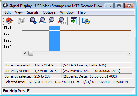
USB Signal Display Window
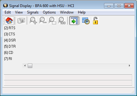
HSU Signal Display Window
When using the SST interface cards for analyzing DeviceNet traffic, the following signals are displayed:
- BP - Bus Power
- OL - Online
- BW - Bus warning, either the receive or transmit error counter (incremented and decremented at various rates according to the Bosch CAN specification) has reached 128.
- BO - Bus off, either the receive or transmit error counter has reached 255 and the CAN chip has been forced offline.
- RO - Receive buffer overrun, one or more messages has been lost due to a full queue in the on-card firmware.
- ML - Message lost, one or more messages has been lost due to a slow interrupt response by the on-card firmware.
- ER - Error, one or more CAN error frames has been detected.
Note: The messages received by NetDecoder are still correct when the ER flag shows some activity, as re-transmission is automatic and only error-free frames result in a receive interrupt from the CAN controller.